I count the optical mouse among the more significant developments in computer history. People today will never know the pain of using a mouse with accumulated gunk on the rollers.
At my high school, they started supergluing the compartments shut to prevent tampering, so I had to carry a Phillips screwdriver and remove the whole bottom to get a usable mouse.
There was a crud-free mechanical design by Hawley, most commonly seen with VAX and DECstation computers. Patent 4,628,755 (and maybe 3,892,963) describes it and probably prevented popular usage.
I know that until optical mice matured and high-precision optical mice appeared, there were many gamers who still preferred mechanical mice (with a ball) since they felt they were more precise and less error-prone (i.e. cursor suddenly moving when it should not or the other way round), though mechanical mouses were a lot more high-maintenance.
I personally have a decent optical mouse on my desk, but also another (rather recently bought) optical mouse that sometimes "stutters" - this may be related to the material of my desk pad (in other words: If I were to buy a good mouse pad the problem would disappear). But this should deliver further evidence for the previous paragraph.
The first camera based optical mouse was the Microsoft Intellimouse. They released various types all with the same sensor. These were superb mice for the time, and still good by modern standards. Unlike a lot of competitors (even today) the sensor had pure linear response, no smoothing, no angle snapping, no forced acceleration. It was ideal for gaming. It couldn't cope with very fast movement but it was possible to poll the USB port at a higher frequency which increased the maximum speed before error. 500Hz polling was popular (supported in Linux with the usbhid module's mousepoll option, available with hacked drivers in Windows). The sensor resolution was a somewhat low 400DPI but with the display resolutions people played at back then it wasn't a major issue.
Any problems with erratic movement were caused by excessively shiny surfaces. Preferring ball mice was pure superstition. All the competitive players switched once they realized how much better the optical mice were. I still use an Intellimouse today (with replaced microswitches after the originals wore out).
If you play with low sensitivity it's plenty, but the Intellimouse family wasn't well suited to low sensitivity because it loses linearity if you move it too fast. With high sensitivity you can notice the imprecision. There's a middle ground where there's no problem, but sensitivity is a personal preference and you might not like that sensitivity.
Check whether you can increase the Lift-Off Distance (LOD) in the mouse's configuration.
I have a good quality mouse pad, but that specific material, combined with the specific sensor in my mouse meant that having an LOD setting of 1 (it's a scale value from one to 5) would make the mouse work fine, except for intermittent stuttering that made me think there was dust on the sensor.
Disclaimer: I had to download the mouse's Win-only utility to change this setting.
Yeah. Those chips usually talk via SPI. There's interestingly a lot of options, including ways to boost quality. One sucky thing, is they use "dots per inch" which is just completely stupid and boneheaded - seriously... Inches?!
But the ones I'm using are the ADNS-5030 for an interesting project with 3d printing. Its max poll rate is 1MHz, which is damned quick for a Atmel328p chip- it leaves only 16 instructions per SPI poll. The chip's default is 500 DPI (grr again inches), but can be changed simply by popping a "1" in a register.I'm sure different chips have much better qualities.
Also, you can pull out the dX and dY registers for relative travel since last sample. But you can also pull 256 times to get a 7bit grayscale picture of the mouse sensor! ADNS-5030 is a 16x16 7bit grayscale. And even the 'duino can pull that with relative ease and display in Processing. You can also display the fiduciary markers in which the optical analysis system determines as travel (how it gets the dX and dY).
But yeah, this article is kind worthless. Sorry. Anyways, videos can be a really bad way to pack little content in a lot of time and bandwidth. :/
You're not trying to get absolute position from those sensors, are you? I spent far too long on that project. At least at the precision we needed, my conclusion was that you would want to acquire and process the images yourself - both to get a higher resolution/field-of-view, and to estimate the error associated with each position update (Kalman filtering or similar). You can also then "re-register" your position if your path travels over the same spot twice.
These "mouse" sensors not only allow motion detection of small mice, motion detection of larger object and faster movement are possible too, which I think is a interesting application:
Speaking of interesting applications, the Roomba 980 uses an optical tracking sensor in order to improve the accuracy of its mapping -- inconsistently gripping wheels make it impossible to navigate accurately on earlier models (hence the "bounce around randomly" approach) but watching the floor move past gives far more accurate positioning data than simply counting wheel rotations.
They're really neat and there are tons of applications, but I've never been able to find good, usable packages to use with my own projects. Once in a blue moon one of the usual suspects will release a custom board. I just wish I could easily order assemblies from digikey, et al.
yes thats what I meant, I checked ebay and it seems I have outdated information, there _was_ a kit based on mouse sensor, but its no longer available. There are camera kits now providing same function, probably thanks to jump in cheap processing power (16mhz avr VS 180mhz arm f4).
That answer is talking about the sensors used in mechanical mice, not optical mice. (Most mechanical mice did use optoelectronic sensors, but nobody would call the mice "optical" just for that.)
Is it possible to make like a cheap electric pen using parts from optical mouse? Currently there is Nebo app [1] available for free from Microsoft Store, but it requires touch/pen device. Doesn't work with mouse :(
I wonder how the "pixel matrix + laser diode + image processing part" & similar products are designed. Is it done using a specialized graphical CAD software or with a language such as VHDL? Or a combination of both?
It depends on the specific application and of course your requirements. In general, there two ways to design a ASIC.
The more common approach is called semi-custom design. The idea is to write your gate-level design in VHDL, and simulate it extensively to make sure it works. Once you want your circuit to be realized, you pipe that code to a synthesis tool that does a place-and-route. In a nutshell, the synthesis tool takes each gate, converts it to its transistor layout level design using a standard cell library, and finally routes the gates (or cells) together to realize the connections between them. The tool would then perform a LVS check which makes sure that the layout performs the same function as the HDL code you wrote. Finally, the synthesizer outputs a GDS file which describes the exact layout specifications, including transistor dimensions, spacing, and placement on the silicon die. You send this GDS file to a fab and voila you get a circuit!
The other approach is much less common nowadays in digital circuit design, and is limited to applications where performance is key. It is known as full-custom design. You basically design the circuit at the transistor level by hand, and then simulate it to make sure it works. After that you manually design the layout of that circuit, and as before perform a LVS check. Your EDA tool will package your layout into a GDS file which you again send to the fab for manufacturing.
For example, in a modern CPU, key circuit components such as adders, multipliers, dividers, multiplexers, encoders, flip-flops, and cache memory are usually designed using a full-custom approach for maximum efficiency and performance. Other general circuitry may be designed using semi-custom. It also varies by company. I believe that ARM processors are completely designed using standard cells, not sure about Intel/AMD though.
I know ten years ago you could get standard cells for various peripherals and processors that were known good for the process you were going to use. Advantage is known good working part with documentation, probably test vectors as well.
Might be hard to say about the chips used for optical mice. First article I read on them was about 20 years ago in maybe Electronic Design News or some such.
Deal with these is because of the image sensor and analog driver circuitry need a certain amount of real-estate, and the requirements don't change much, they might just occasionally tweak the design to make it work with whatever fab process is cheapest. AKA they could be using really old layouts/designs.
I've only ever used the low end tools for FPGA parts, but even when you design with an HDL, the output is realized in stages. It translates your code, then determines a netlist, then does physical layout and routing, then it can produce either a bitstream output for something like an FPGA, or one of several outputs that can be sent to a fabrication plant for ASIC production.
For the image processing "state machine" I imagine most of the "core" design is done at the HDL level with some small tweaks to the other steps along the way to optimize the chip for physical production.
Could a mouse's optical sensor be used for a fairly accurate way to track how far a motor has turned? I've seen hall effect sensor used for this, but for slower things I wonder if a mouse could work.
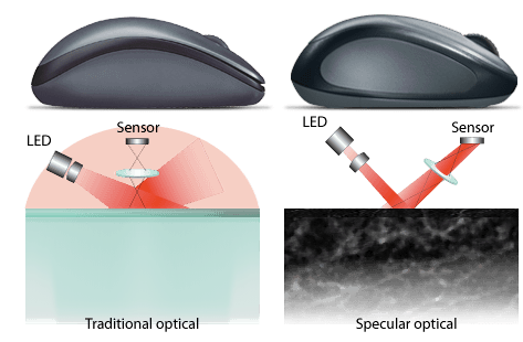
The old optical mice used IR to detect the grid lines on the old mouse pads. Today's mice take an image of the surface, and compare it to another image taken quickly after. Faster chips/better optics enabled this.
Not sure if you mean on the hardware side or on the computer, the Teensy is a family of small dev boards which are easy to work with in the Arduino IDE, and can emulate USB HID devices (including mouse and/or keyboard) [1]
At my high school, they started supergluing the compartments shut to prevent tampering, so I had to carry a Phillips screwdriver and remove the whole bottom to get a usable mouse.